Layout Point
Layout Points are used to define custom layouts for Wires, Dimmed Wires, and Cables in the Schematic View, and for Bundles in the Layout View.
Adding a Layout Point
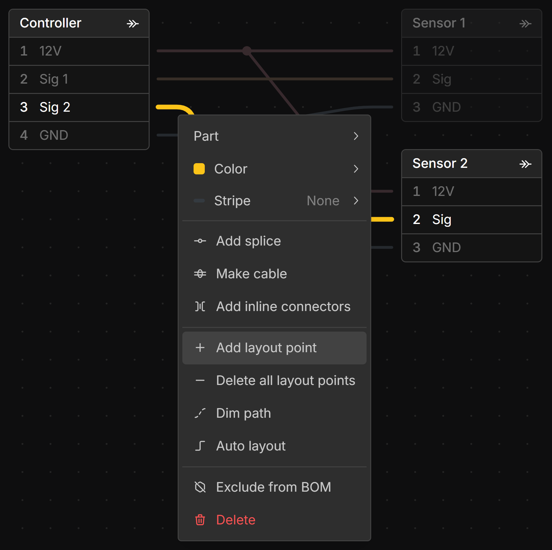
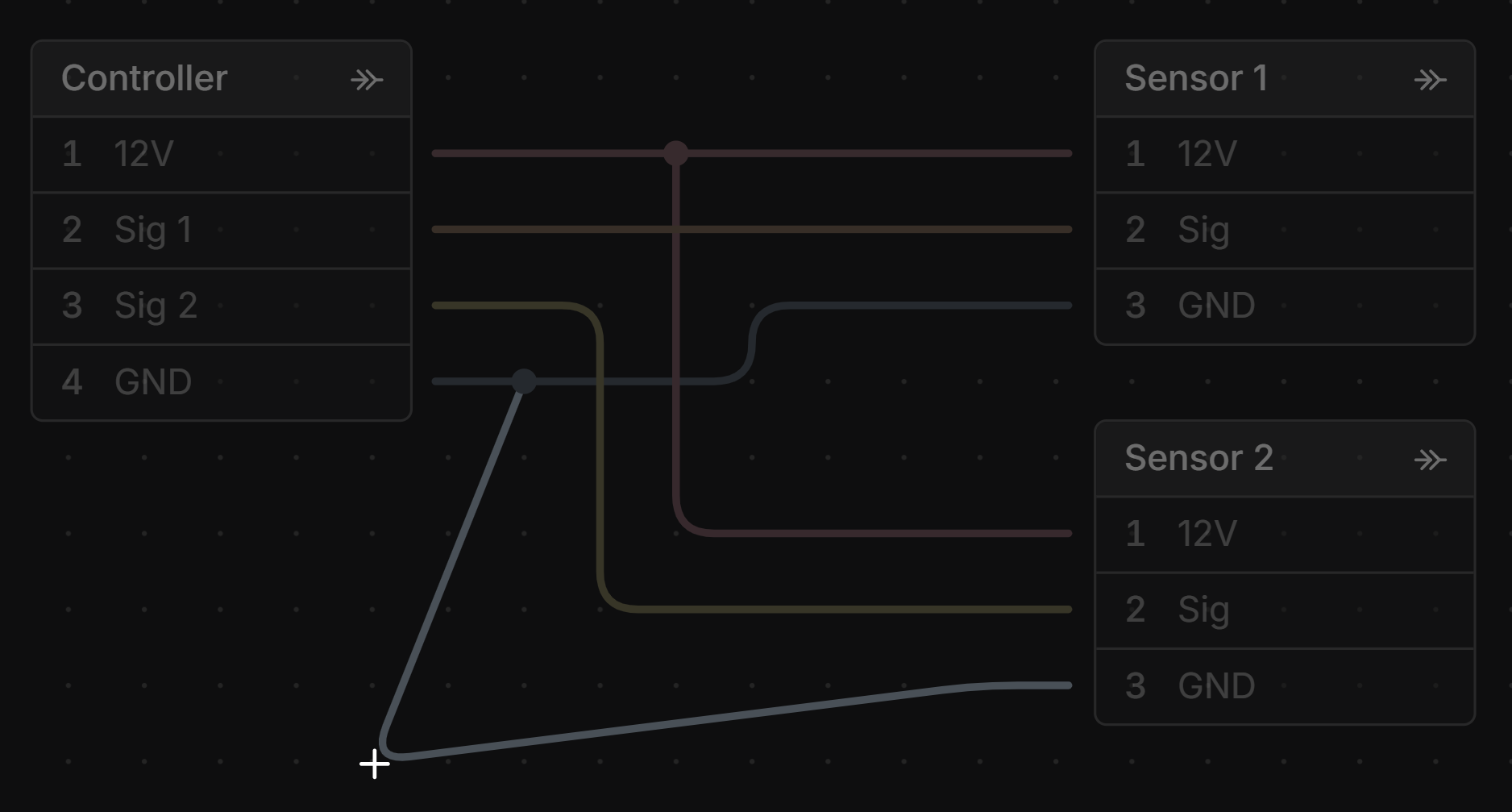
Double-click a Wire, Dimmed Wire, Cable, or Bundle to add a Layout Point. You can also right-click the item and select Add layout point from the context menu.
More than one Layout Point can be added to a wire for more complex routing.
Moving Layout Points
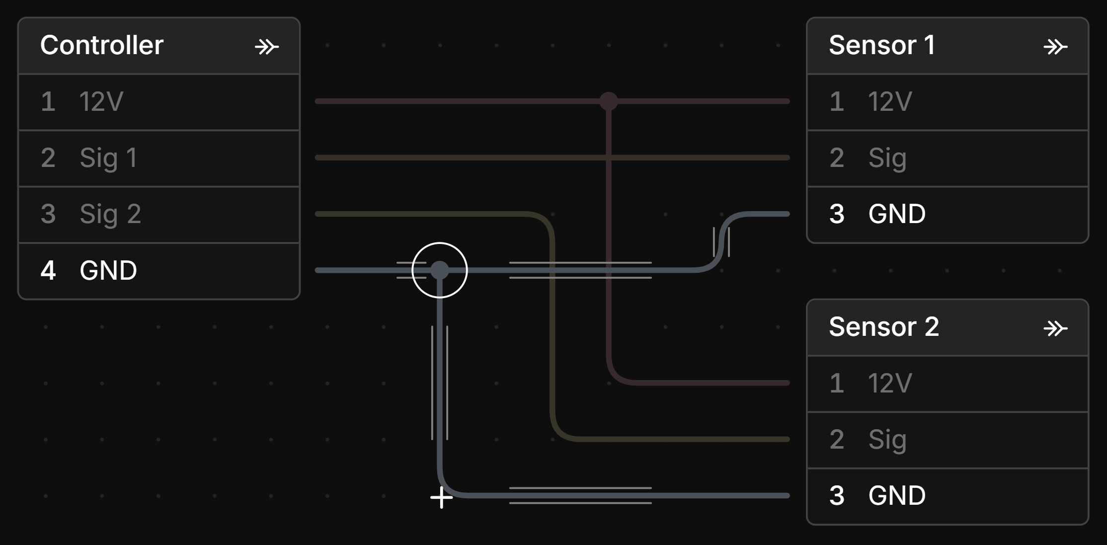
To move a Layout Point, click and drag it to the desired position.
You can shift-click to select, or marquee select, to move multiple Layout Points at once.
When moving a Layout Point, parallel guide lines will appear on the sides of the item being adjusted when it is aligned horizontally, vertically, or at 45°.
Left-clicking and dragging on a Wire, Dimmed Wire, or Cable will move the two layout points on either side of the dragged position.
Deleting Layout Points
To delete a Layout Point, select it and press the Delete key, or right-click the point and select Delete.

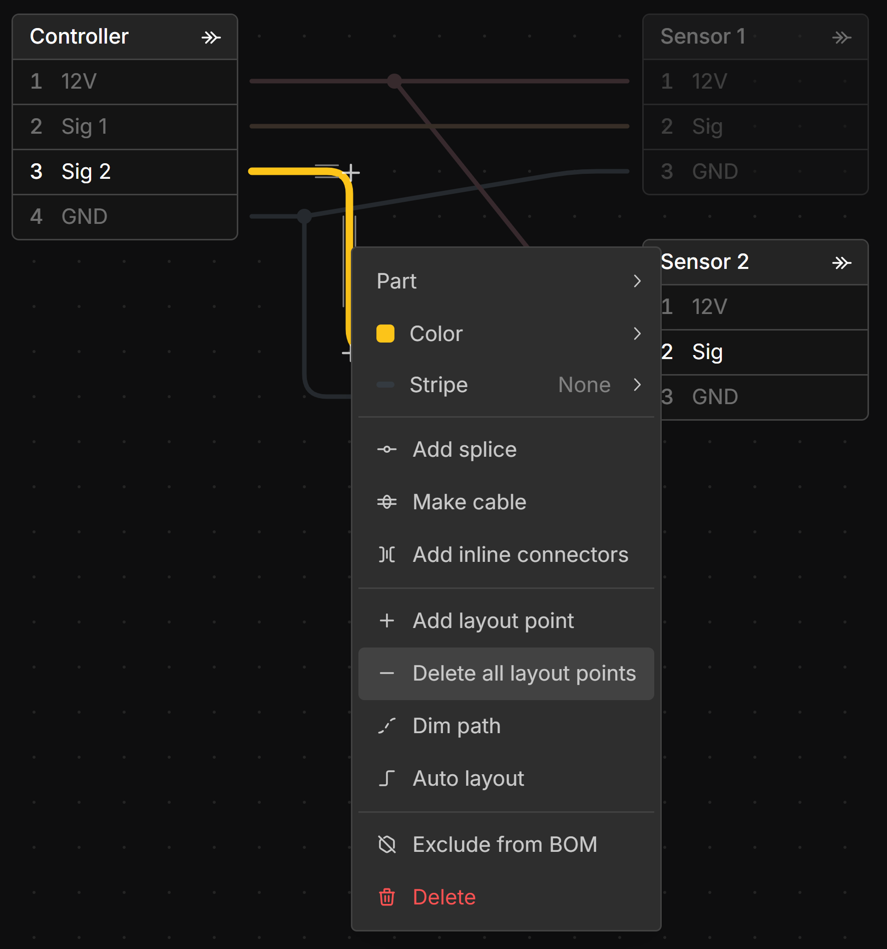
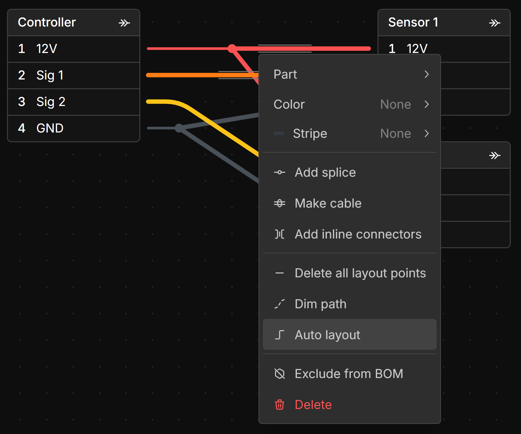
You can delete all layout points on a Wire, Dimmed Wire, Cable, or Bundle by right-clicking the item and selecting Delete all layout points from the context menu.
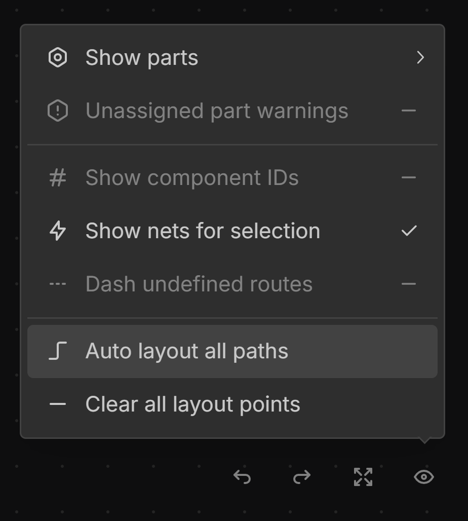
You can delete all layout points from the Schematic View or Layout View by clicking Clear all layout points from the View Options menu.
Auto Layout
To auto layout a Wire, Dimmed Wire, or Cable in an orthogonal manner, select the items you want to lay out, right-click, and select Auto layout from the context menu.
You can auto layout all wires on the schematic by clicking Auto layout all paths from the View Options menu in the Schematic View.
Auto layout only works in the Schematic View.