Connector Part
This represents the housing of a connector. A connector contains cavities to which contacts or cavity plugs can be assigned. It can accept accessories such as locks, dust covers, boots, backshells and mounts.
| Property | Description |
|---|---|
| Part Number | Unique identifier for the connector part |
| Internal Part No. | Your own identifier for the part, e.g. a stores or ERP number. Read more… |
| Manufacturer | Company that produces the part |
| Description | Description of the connector part |
| URL | Link to datasheet or manufacturer website |
| Price | Unit price of part |
| Cavities | Total number of cavities in the connector |
| Designations | Labels used to identify each cavity (e.g. 1, 2, 3 or A1, B2). Read more… |
| Gender | Specifies whether the connector is male or female |
| Shell | Allows a wire to be directly connected to the housing of the connector (ie the ground connection on a coaxial connector) |
| Color | Color of the connector housing |
Assigning to a Component
See Assigning Parts
Connector Configurations
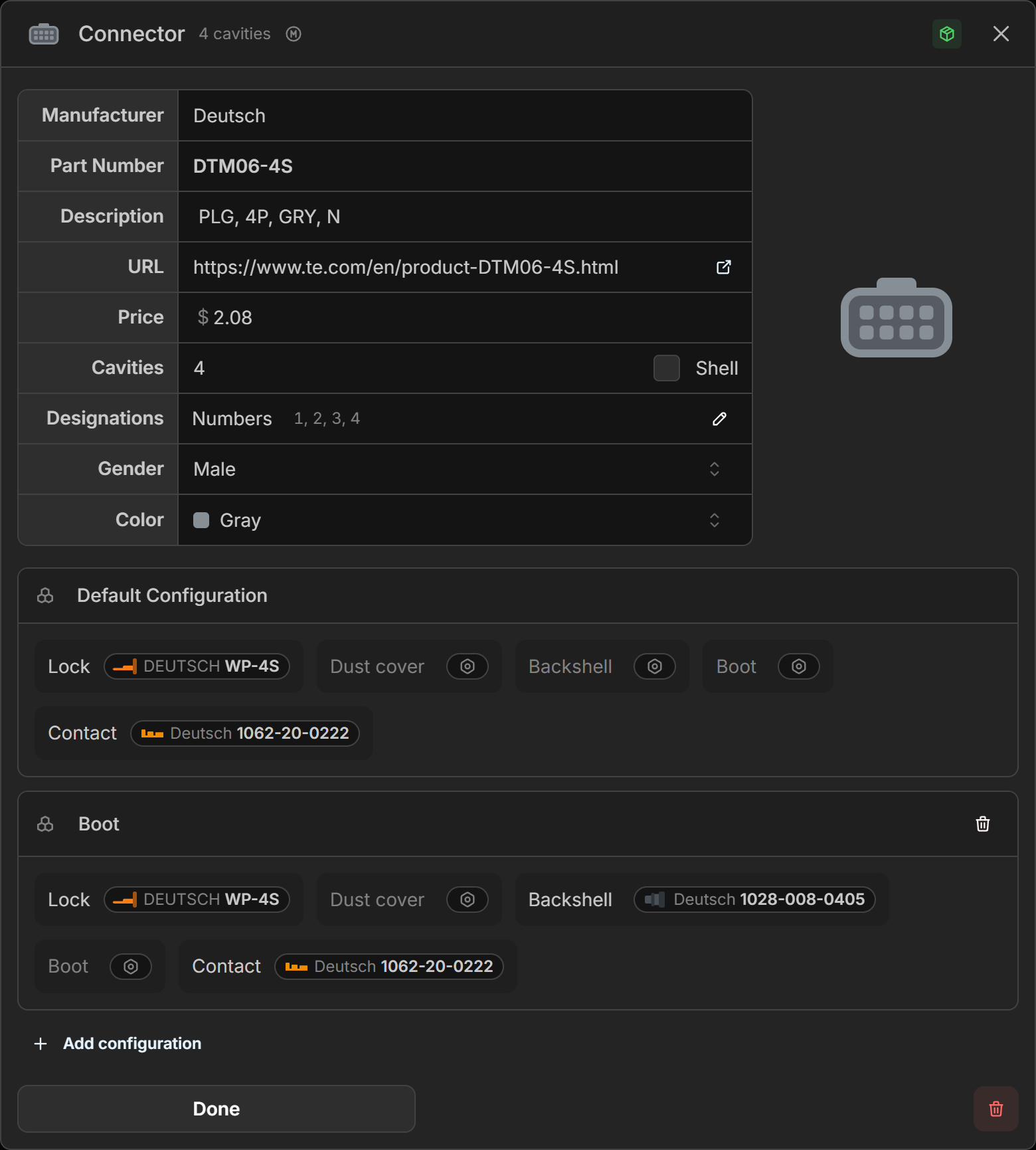
A Connector Configuration defines a set of default parts to bundle with a connector part. When a connector part is assigned to a Connector, any parts defined in the selected configuration are automatically applied to it.
Each connector part includes a Default Configuration. Additional configurations can be added to represent different assembly variants, for example, a sealed variant with a boot and backshell and an unsealed variant without.
Adding a Configuration
Click Add configuration to create a new configuration and give it a name.
Duplicating a Configuration
Click Duplicate configuration to duplicate the selected configuration.
Deleting a Configuration
Click Delete next to the configuration you wish to remove.
Adding Parts to a Configuration
Click Part button to select or search for a part from the drop down.
Unassign Parts to a Configuration
Click the part you wish to remove and select Unassign part.
Cavity Designations
Cavity Designations are the labels used to identify each cavity in a connector. When a connector part is assigned to a Connector, the connector inherits these designations.
Click the button next to the Designations property to open the designations editor.
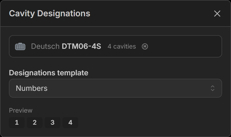
The following templates are available:
- Numbers: Sequential numbers (e.g. 1, 2, 3, 4). Choose Start at
0to number from zero instead (0, 1, 2, 3). - Alphabetical: Sequential letters (e.g. A, B, C, D). Case and case behavior can be adjusted. Letters that may be confused with numbers can be optionally skipped.
- Grid: A row and column grid (e.g. A1, A2, B1, B2). The count and label style for rows and columns are configured independently, including the Start at value for numbered rows or columns.
- Custom: Enter a label for each cavity individually.