Connector
A Connector joins electrical parts, allowing easy connection and disconnection of circuits. It serves as a termination point in the harness. Connectors can be assigned a Connector Part.
The following parts can be assigned through a Connector Configuration and are automatically applied to any Connector Component when that Connector Part is assigned.
- Contact Part - Connectors can have multiple cavities, and each cavity that has a connection is assigned a contact.
- Cavity Plug Part - A cavity plug seals each cavity that has no connection.
- Lock Part - Some connectors require a lock to secure the contacts in place.
- Dust Cover Part - A dust cover can be added to connectors to protect the contacts when unmated.
- Boot Part - A boot, which is soft, mounts to a connector for strain relief and sealing.
- Backshell Part - A backshell, which is rigid, mounts to a connector for strain relief and sealing.
- Mount Part - A mount is the clip or bracket that fixes the connector in place when the harness is installed.
- Covering - Coverings can be applied to a connector.
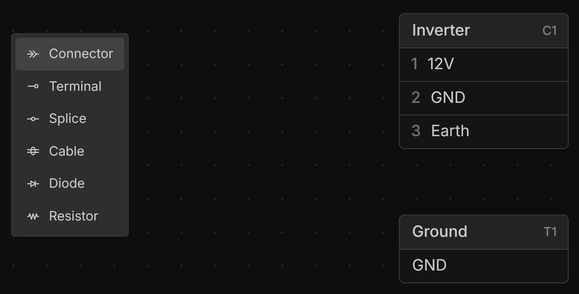
Adding a Connector
right-click on the canvas in the Schematic or Layout view and select Connector.
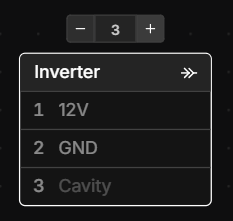
Adding and Removing Cavities
Select a connector in the Schematic view, then click the or buttons to add or remove cavities. Type in the number of cavities you want directly into the cavity count box to quickly set the number of cavities.
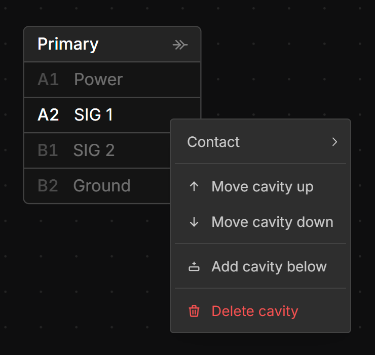
Reordering, Inserting and Deleting Cavities
right-click on the cavity you want to reorder and select Move cavity up, Move cavity down, Add cavity below or Delete cavity.
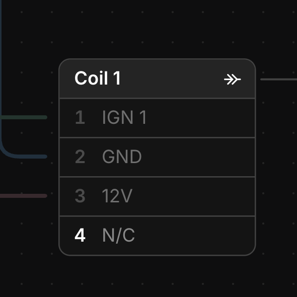
Not Connected Cavities
Cavities that are intentionally left unused can be marked N/C. right-click the cavity and select Mark as not connected. The cavity shows a dimmed N/C label in place of its signal, its connection handle is disabled, and it is skipped when tabbing through signals. An N/C cavity is treated as unwired everywhere: it takes the configuration’s cavity plug rather than a contact, raises no “unconnected cavity” warning, and is shown as N/C in the Connections view, the wiring table and the PDF.
A cavity with a connection has to be disconnected before it can be marked N/C. To use the cavity again, right-click it and select Clear not connected.
Connecting to the Shell of a Connector
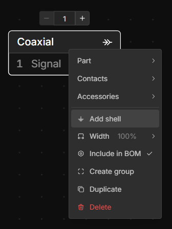
right-click on the connector and select Add Shell
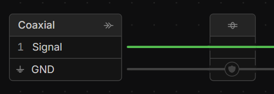
Shells can be connected to just like cavities.
Editing Connector and Cavity Names
left-double-click any Connector Name or Cavity Label to edit it. Pressing tab will move to the next label, pressing shift tab will move to the previous label.
To label many cavities at once, paste a column of names copied from a spreadsheet into a cavity’s signal field. Each line fills the next cavity down.
Editing Cavity Designations
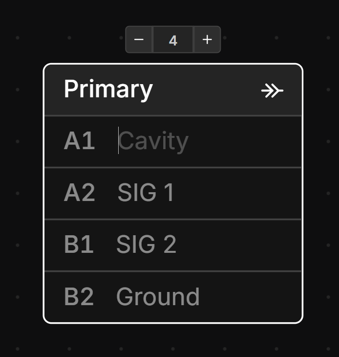
Cavity Designations are the labels used to identify each cavity in a connector (the pin numbers, e.g. 1, 2, 3 or A1, B2).
How you edit them depends on whether a Connector Part is assigned:
- No part assigned -
left-clicka designation label and type any value. Each cavity can be set individually. - Part assigned - the connector inherits its designations from the part, so they can no longer be edited directly on the component. To change them, edit the part’s Designations property — see Cavity Designations.
Assigning an existing Connector Part overwrites any designations you entered manually with the designations defined on the part. However, if you create a new part from the connector, your manually entered designations are copied across to the new part.
Adjusting the Width of a Connector
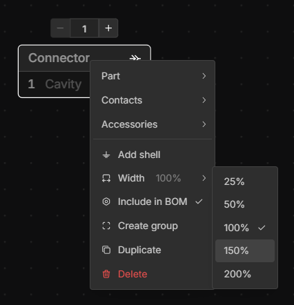
If the name or cavity labels are too long to fit, right-click the connector, select Width, and select the desired width %.
Rotating a Connector
Connectors can be rotated 90° in the Schematic view to improve complex layouts. To rotate, right-click a Connector and select Rotate or select a connector and hit the R key.
Adding Inline Connectors to Wires
You can add inline connectors by selecting the Wires you would like add the inline connectors to, right-click, and selecting Add inline connectors.
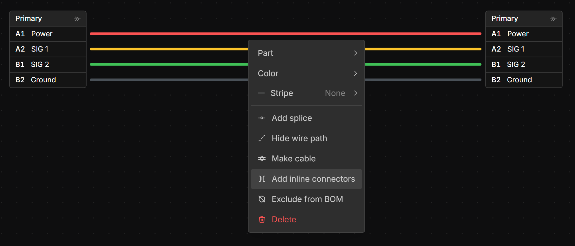
This will add inline connectors to all selected wires.

Adding Inline Connectors to a Bundle
You can add inline connectors by selecting the Bundle you would like add the inline connectors to, right-click, and selecting Add inline connectors.
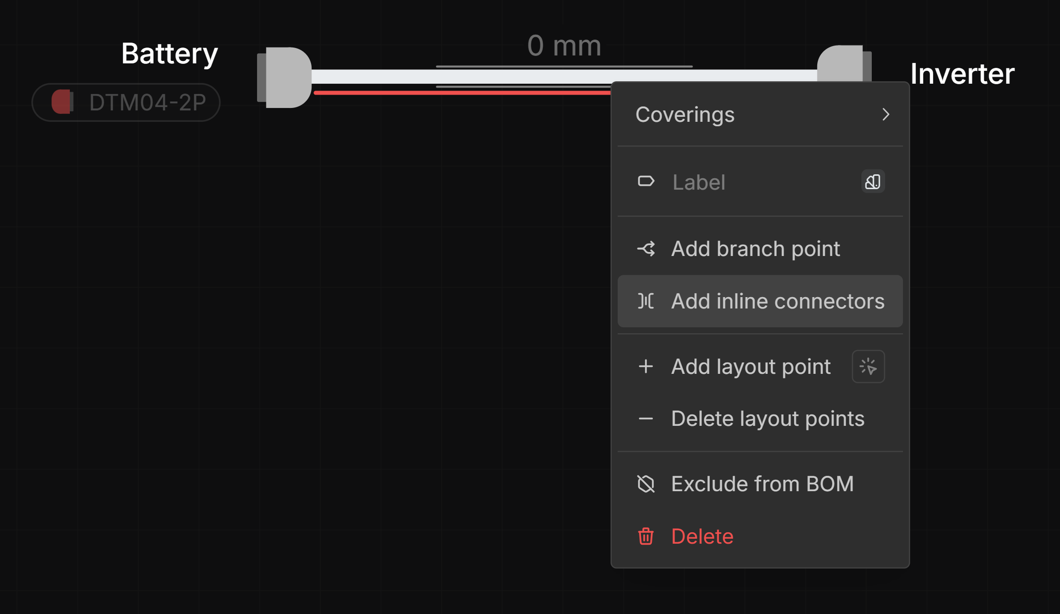
Mating a Connector
To mate a Connector to another connector see Mates.